|
|
| Home-->F1 Rocket Project-->Engine Page 7 |
|
SITE CONTENTS
Please send your comments and suggestions to: Copyright
© 2008 by
|
Links
on this page: Oil Dipstick Door Cowl Scoop Air Box |
|
|
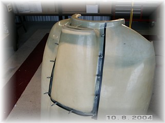
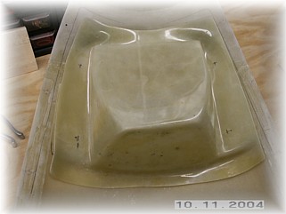
When it came to the oil dipstick door, I decided to do mine different than what the plans show. I don't like the hinge showing on top of the cowl for a couple of reasons. The primary reason is that after a short period of time, the hinge will streak the cowl with what looks like black dust, which is probably the wear and dirt on the hinge pin. So instead, I'm going to build a hidden hinge on my door.
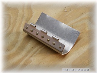
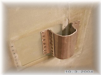
First, I cut the oil door out based upon the scribe lines. Then, I cut the opening in the cowl leaving about 1/2 inch all the way around. Then I fabricated an extended hinge part. While I was at it, I laid down an 8-ply reinforcement for my internal hinge into the top of the cowl. The idea here is that the hinge pivot point is behind the edge of the door. This allows it to swing up and away from the cowl. I had to play with this for a couple of hours until I figured it out. In the pictures, ignore all the holes in the door recess. These are goofs that I will fill with filler once I finish the cowl.
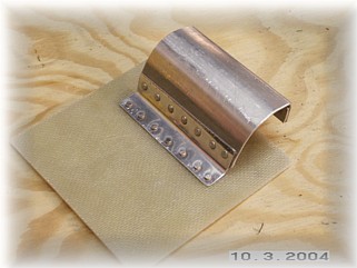
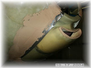
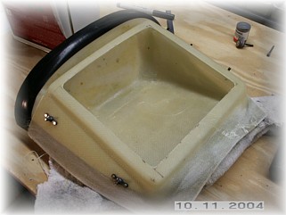
I then riveted the hinge to the backside of the oil door and the base hinge to the inside of the top of the cowl.
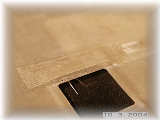
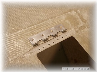
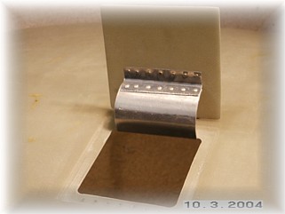
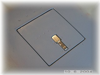
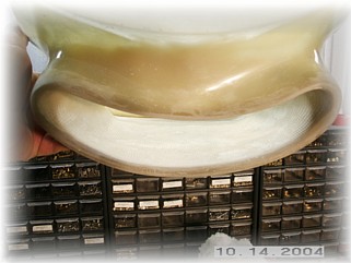
This is what the completed assembly looks like from underneath when the door is closed. All I have to remember is to allow room for this hinge in my plenum. I riveted this up pretty sturdy because I'm still not 100% sure I'm building a plenum so I wanted it to be strong enough to hold the pressure of the baffles in case I change my mind. It's probably a little overkill here.
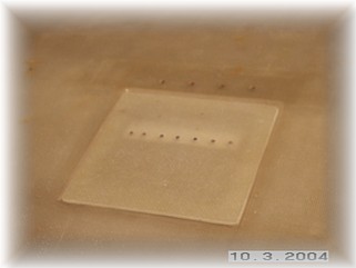
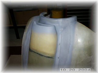
Here's the finished door. It swings up and the back of the door hits the top of the cowl at the same time the inside of the hinge hits the inside lip.
I added a Harwell latch to hold the door closed and then finished the door and surrounding area. A little bondo, a little spot putty, and a little primer is all that's needed to finish up the door area.
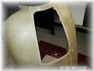
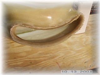
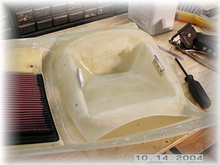
I began by using my Dremel tool and a drum sander and smoothing out the recess in the lower cowl. I wanted to better define the edges of the recess before trimming the scoop. I then trimmed out the scoop. I generally followed the trim lines and then I adjusted the fit to match my lower cowl.
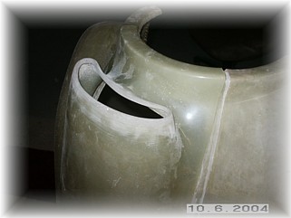
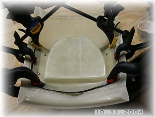
I chose to add one more attach point on each side than those called for in the plans. I think 6+ inches is a little much to span with this fiberglass and I was afraid of eventual warping of the edges after the part was completed. I also diverged from the plans by first drilling the attach holes #40. I then laid up a 2 ply reinforcement on the scoop. While it was wet, I clecoed it to the lower cowl. That way the reinforcement strip will help the part to hold the shape of the cowl. When it dried, I drilled the holes up to #30 and removed it for final trimming and cleaning.
The final step was to slather the area up with micro and sand it smooth. After a little primer, I patched the small holes with spot putty, sanded and primed it again.
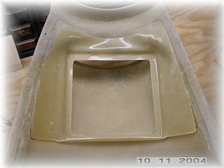
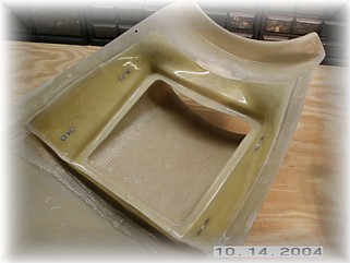
To fit the air box, I first trimmed up the two parts to sit just inside the outline of the flange from the lower cowl. This is pretty much according to plans. I then marked the location for the four mounting holes that hold the cover on.
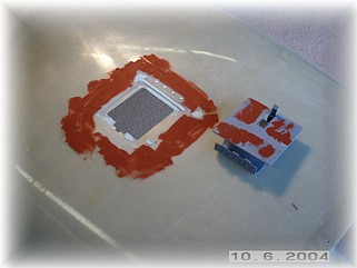
After mounting the nut plates, I taped up the edges of the cover and screwed the two parts together. After roughing up the edges, I floxed the air box tray to the lower cowl scoop and let it set up overnight.
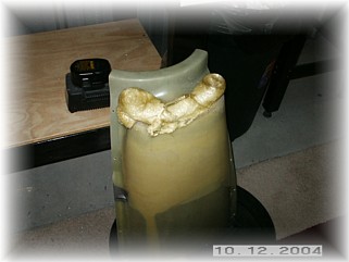
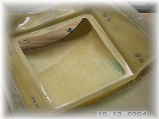
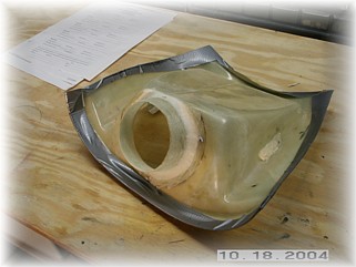
Once the flox dried, I removed the air box cover and taped over the filter cut out with duct tape in preparation for pouring in some A-B foam. Per the instructions, it's important to smooth out the airflow into the filter. I poured in the A-B expanding foam and let it set up, about 30 minutes. Then the fun. I dug, cut, filed, trimmed, gouged, and otherwise mangled the foam until I had removed nearly all of it. I filed a smooth transition from the lip of the scoop up to the four sides of the filter box.
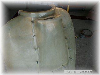
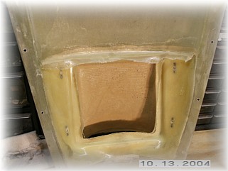
Now came the tricky part. Fiberglassing the foam inside the scoop is not an easy job, but there are a couple of tricks that make the job tolerable. First, I applied a runny mixture of micro to the foam with a squeegee. This is referred to as slurry. This fills the pores of the foam and it gives the glass something to hold on to. Next, I laid up two plies of glass on a sheet of aluminum foil big enough to cover the entire area. I then took the glass plies, flipped them over, and used the aluminum foil to press the glass into the corners and to smooth out the lay up. I trimmed the glass that was overhanging the edges and overlapped the plies along the upper edge of the air inlet. When I had it positioned correctly, I removed the foil and tended to any minor corrections.
After an overnight set up, I trimmed and sanded the rough edges. It turned out pretty nice.
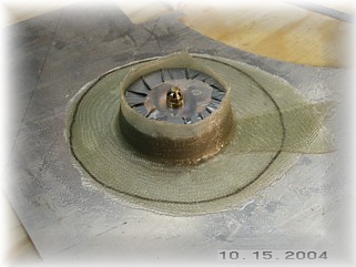
After rounding off the forward edges of the filter per the instructions, I installed two small clips to the side of the cover. With my parts, the forward edge of the cover sits on top of the forward edge of the filter, holding it down. The aft edge of the filter is held in place by the rear edge of the air box, which is tilted slightly forward. So all I needed were a couple of small clips for the sides.
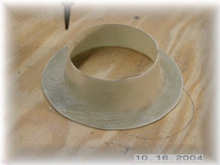
When it came time to install the fiberglass cone for the air inlet, I discovered that I didn't have one. Rather than wait a week for Mark to ship one to me, I just made one myself. A quick 4-ply lay up and an overnight wait was all that was needed.
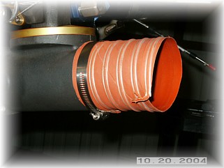
I attached the cone and floxed it into place. The final two steps was to seal the top of the air box with silicone and attach a short piece of SCEET to the Airflow Performance intake. Once everything was installed, I trial fit the lower cowl to the airframe and the air scoop to the cowl. Everything fit just like it should. Now, it's on to the baffles and plenum. That work begins on the next page. |
||
|
"Take your life in your own hands, and what happens? A terrible
thing: no one to blame." |