|
|
| Home-->F1 Rocket Project-->Engine Page 10 |
|
SITE CONTENTS
Please send your comments and suggestions to: Copyright
© 2008 by |
Links
on this page: Ignition Wiring Cooling Tubes |
|
|
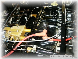
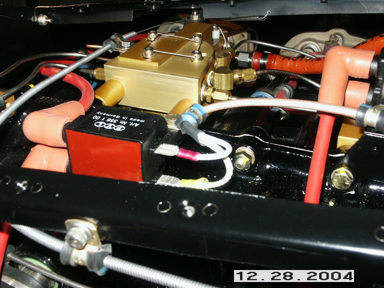
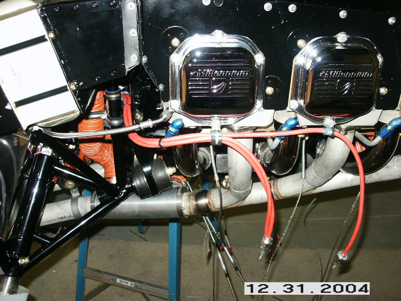
The best place to mount the coils for the Lightspeed Engineering electronic ignition is down the spline of the engine. In fact, the ignition wires supplied with the kit ASSUME that the coils are mounted there. Unfortunately, there's not much room on my engine for them. The coil for cylinders 1 and 2 pretty much mounted to the block with the supplied bracket. For the coil for cylinders 3 and 4, I had to fabricate a bracket that would lift the coil up over the fuel injector lines.
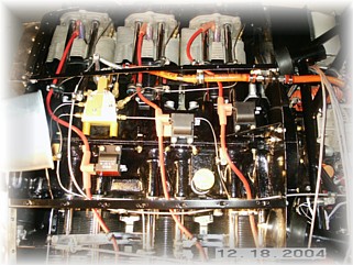
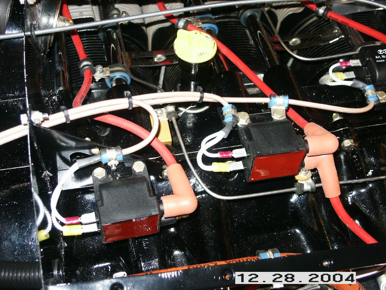
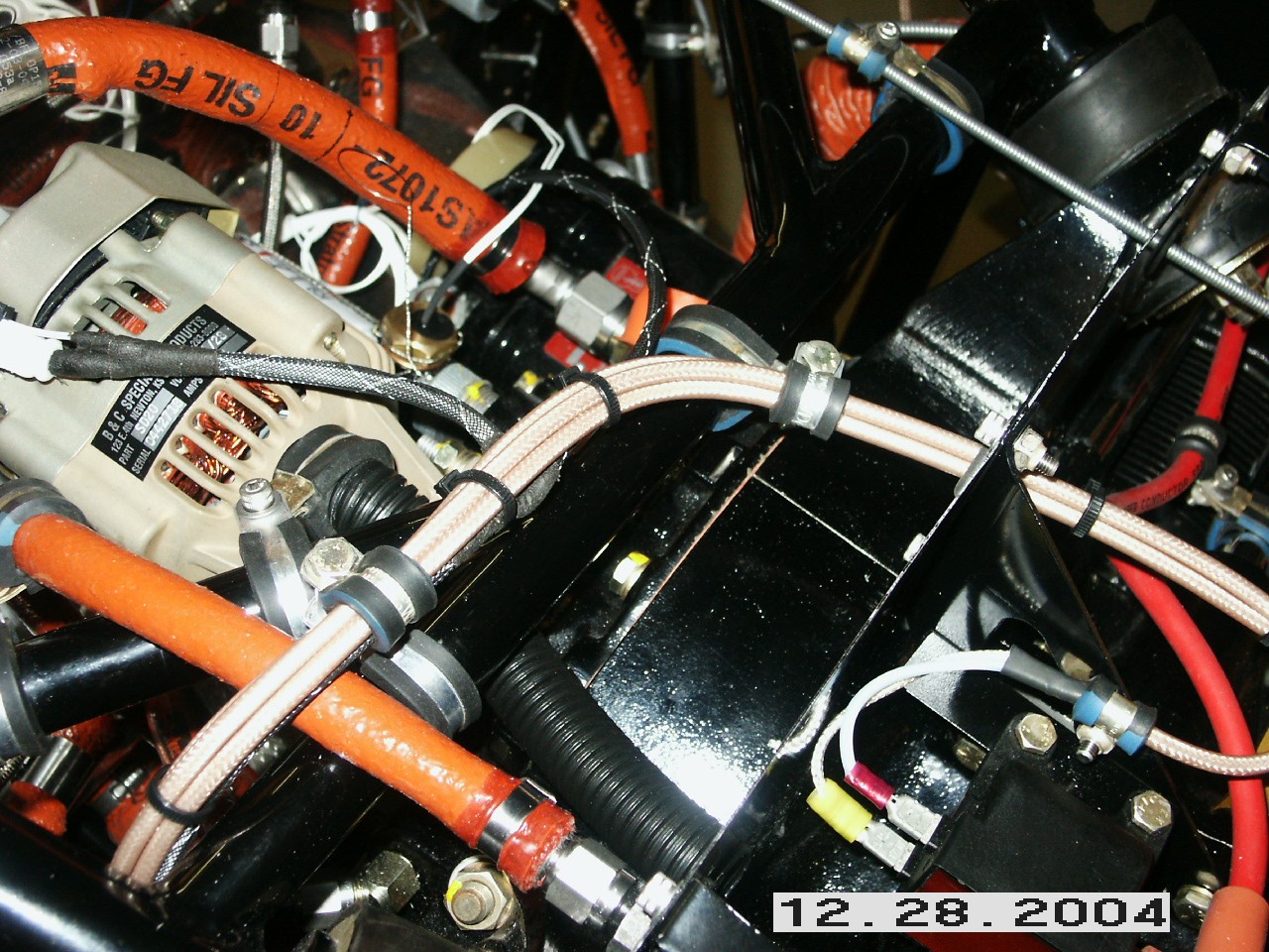
To mount the coil for cylinders 5 and 6, I riveted an piece of angle to the center baffle bracket and bolted it up. I then secured the ignition wires with cushion clamps mounted to the shroud tubes. Have you ever tried to squeeze two cushion clamps together, put a nut on the bottom, and do it all in a cold hangar? My fingers are a mess. The right picture gives you an overview of where I put the coils and ran the wires. Your mileage may vary.
The LSE coils use RG-400 coax wire to connect them to the EI brain box. I routed the wires down the spline and then connected them to the coils.
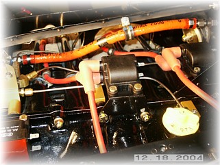
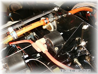
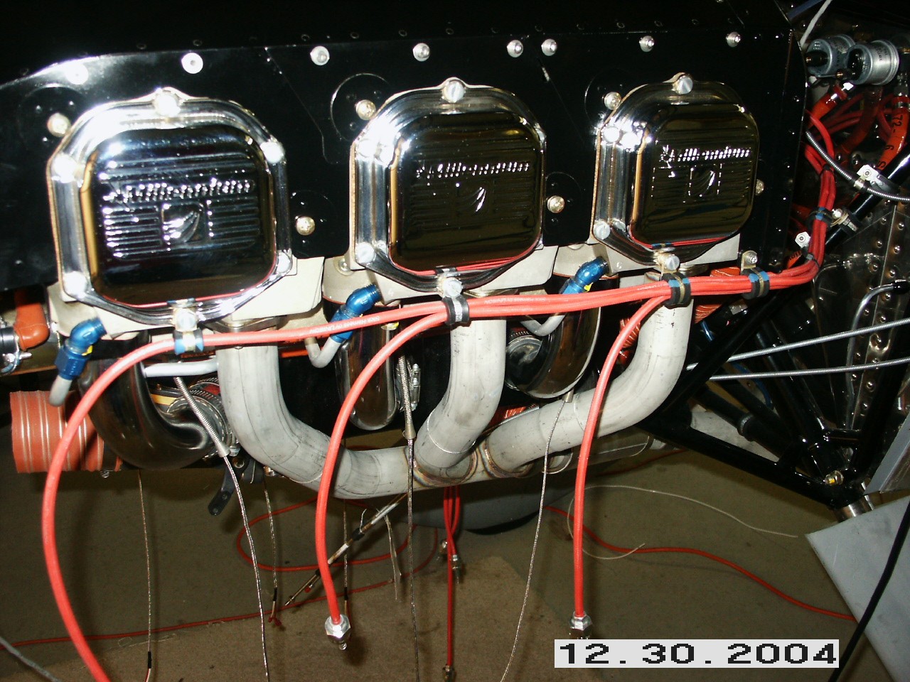
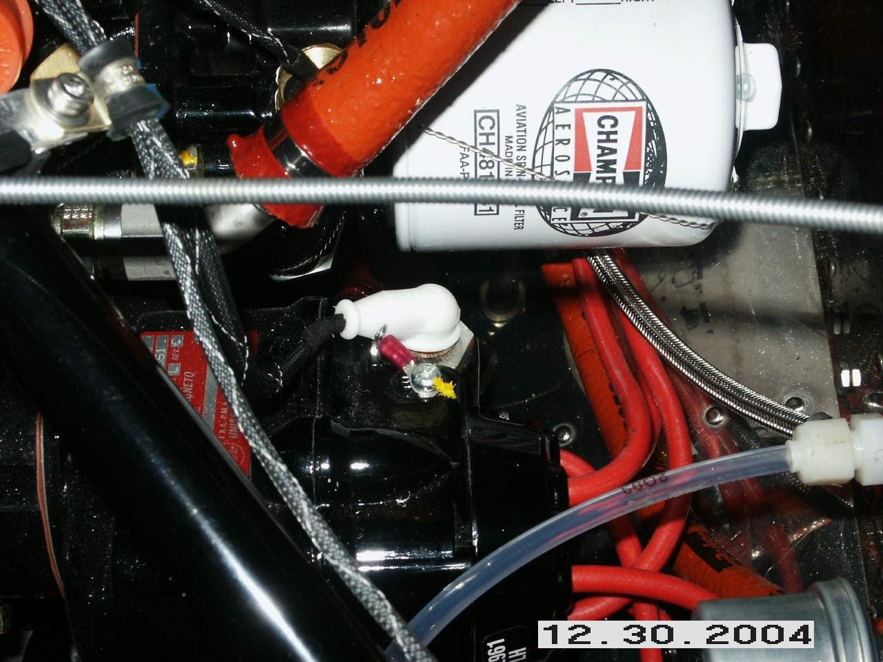
Next, I wired up the magneto. The ignition wires were pre-made by Bart, but I had forgotten how they hooked up. I got out the engine book and found the firing order of the cylinders. Then I bolted the back of the magneto housing on. A couple of notes for those of you not that familiar with Slick magnetos. The wire harness only screws on to the back of the magneto one way, although it has three screws. You have to keep rotating it until all three line up. Also, the No. 1 cylinder wire is stamped on the back. Then, by proceeding counter-clockwise, you can trace where the remaining wires go provided you know the firing order.
This is how I wired up the right side of the engine and how I made the electrical connection to the top of the magneto. Be sure to grind off the paint underneath the ground connection.
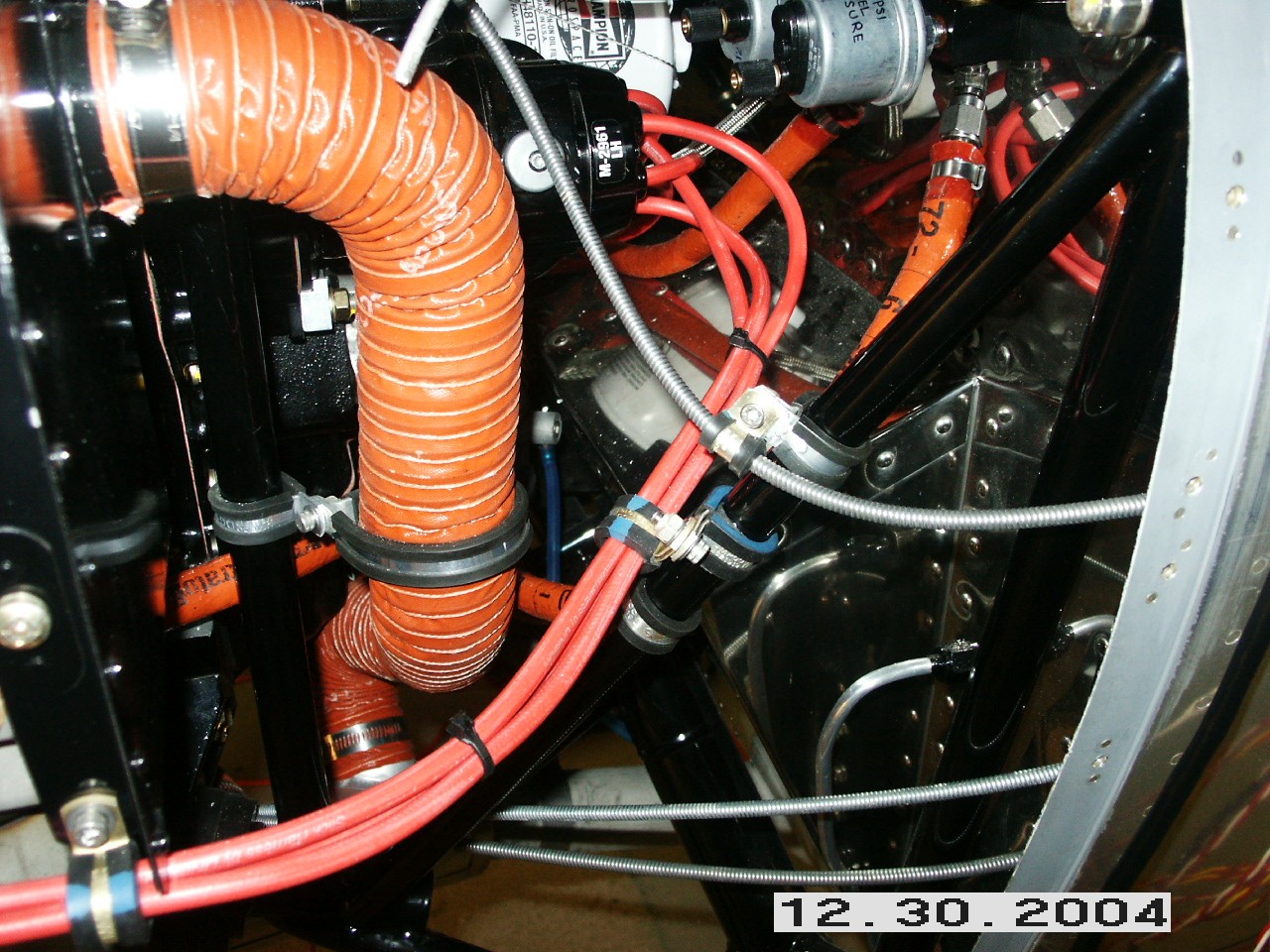
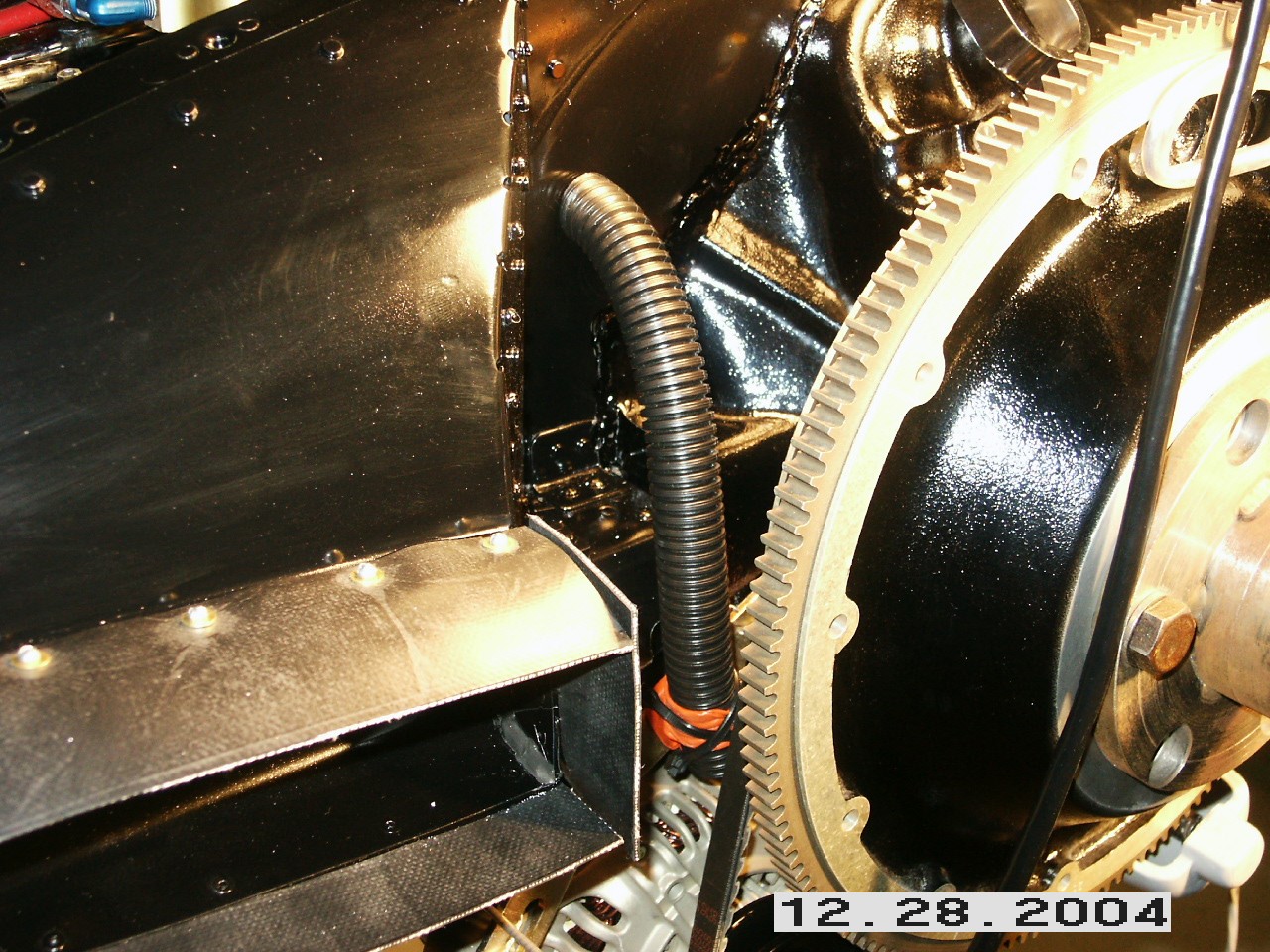
Before closing up the plenum top, I installed two cooling tubes. The first was in front to keep the primary alternator cool. The second one was on top of the engine for the auxiliary alternator. I had planned to put in cooling tubes for the fuel pump and magneto, but I don't think they will be needed. I may add them later. Next, I'll install the crankcase vent and engine controls. That work begins on the next page. |
||
|
"Believe that there's light at the end of the tunnel. Believe
that you may be that light for someone else." |