|
|
| Home-->F1 Rocket Project-->Engine Page 11 |
|
SITE CONTENTS
Please send your comments and suggestions to: Copyright
© 2008 by |
Links
on this page: Crankcase Vent Engine Controls Crankcase Heater |
|
|
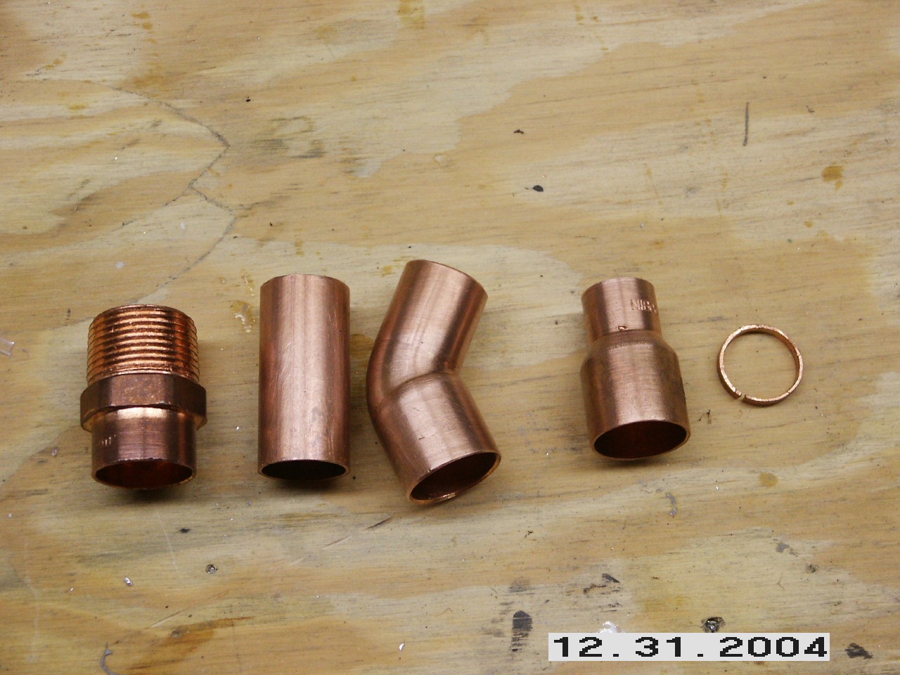
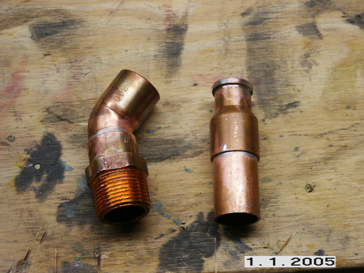
Rather than use the bulky 1 inch tubing fitting that came on the engine, I visited the airplane part isle at Lowe's and picked up the above copper plumbing fixtures. This will allow me to construct a hose fitting that will direct the hose away from the engine block and allow me to use a 3/4" hose as well. First step was to make a small ring to solder on the end of the reducer fitting to act as a hose bib. I then soldered the male pipe fitting and the street elbow together. I also soldered the ring to the end of the reducer and the reducer to a short piece of tube.
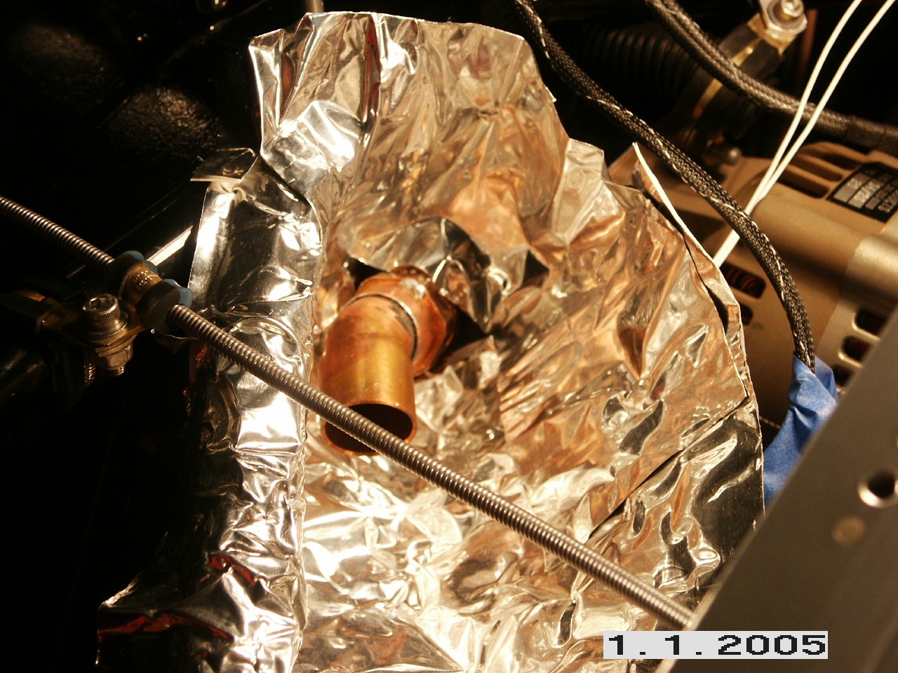
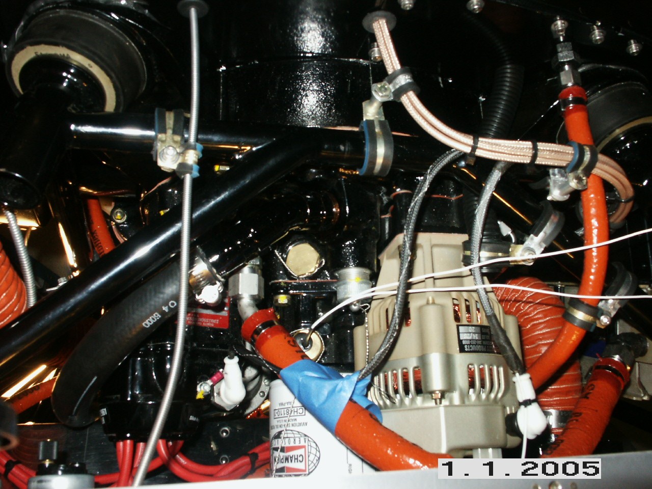
I then screwed the fitting into the crankcase and covered the area with some high temp stainless foil. I carefully soldered the other fitting into the end of the other. You've got to be careful where you point the torch. There's a lot of stuff to melt at this point. The blue tape is just to hold some wiring away from the heat of the torch.
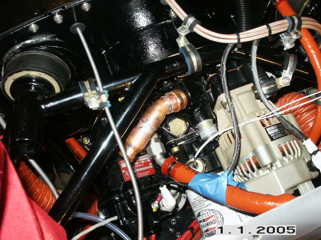
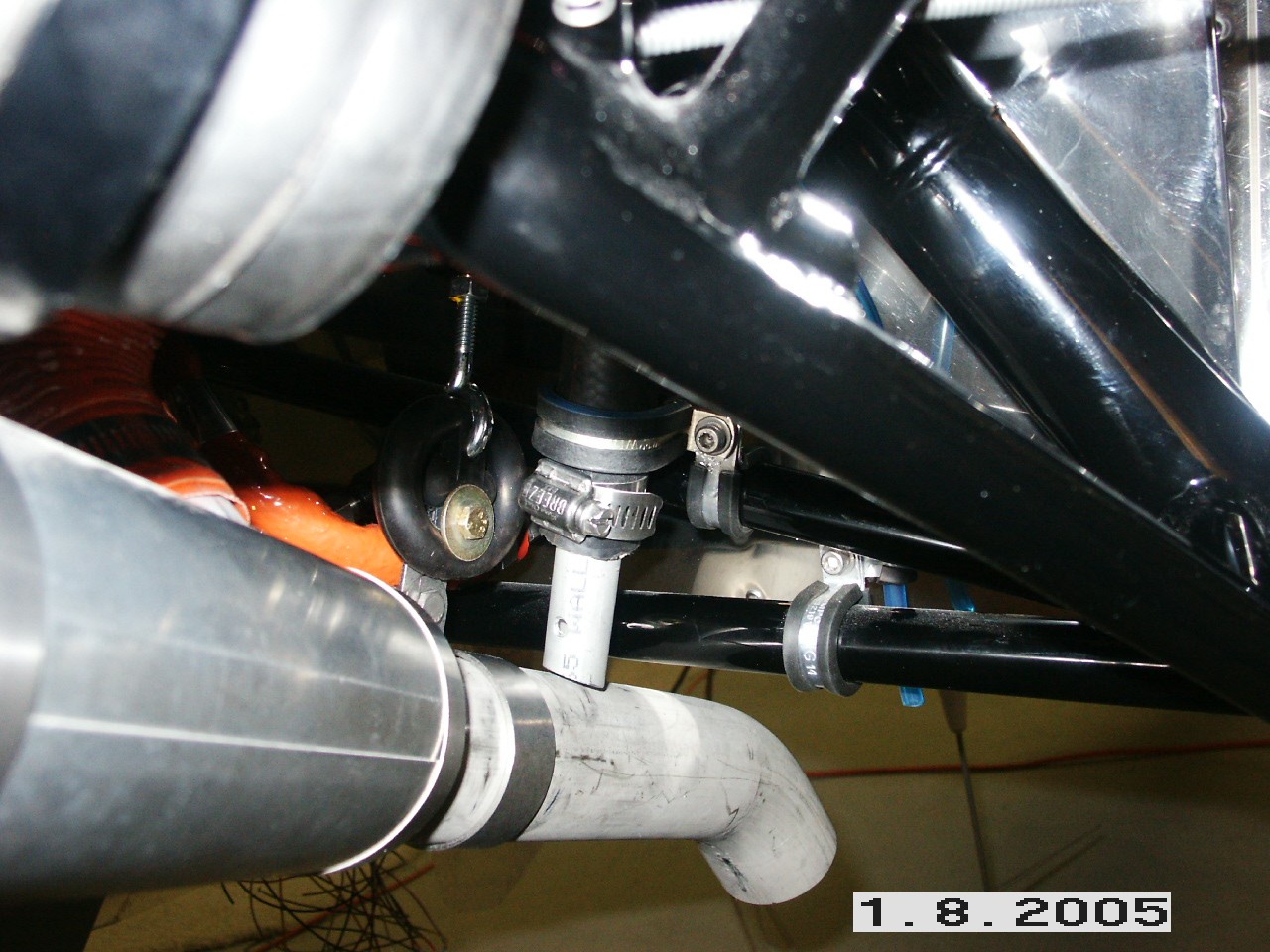
Here's what it looks like all finished with the hose attached. A little black engine paint and it looks like the real thing. Down at the bottom, I inserted an aluminum tube into the bottom of the hose, cut it off at an angle, and drilled a "whistle hole" in the forward facing side of the tube. The entire assembly is cushion clamped to the engine mount.
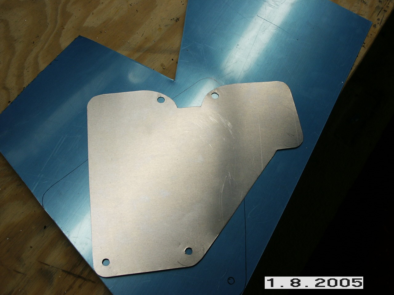
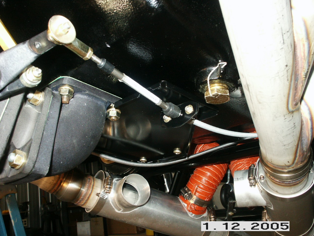
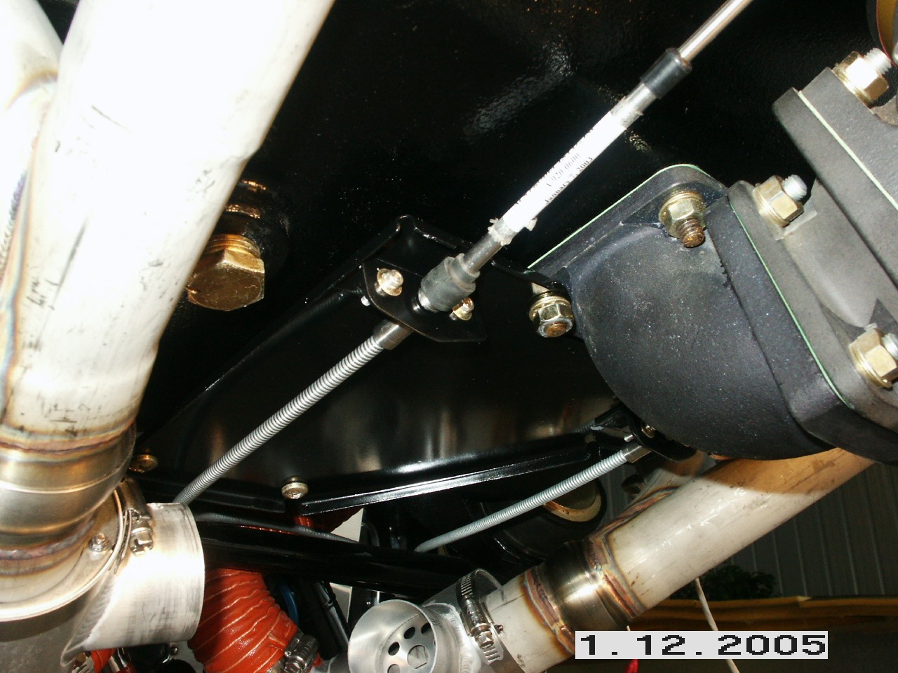
I started out by fabricating a plate that will bolt to the crankcase. Here, I've cut a template out of thinner aluminum and trial fit it to the bottom of the engine. I then transferred that to some thicker material and bent the edges up to provide a little more structural rigidity.
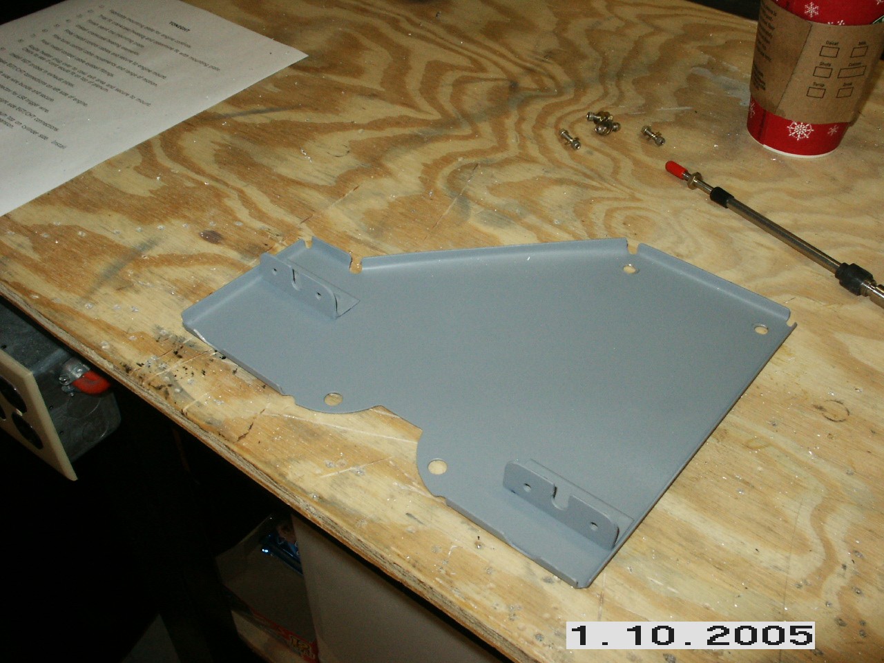
With the base plate finished, the next step was to fabricate a couple of short pieces of angle. I cut some slots in them so that the control cable retainer would slide down inside the slot. I set the throttle at idle cut off and marked the location of the angle on the plate. I then set the mixture control at full rich and again, marked the location of the angle on the plate. I did this with the rod end bearing screwed nearly all the way on the control cable. I then riveted them to the plate.
The last step was to make a couple of flat pieces that also had a slot cut in them and bolted to the angles. This holds the cable retainer in the slot. I painted everything engine black and mounted them. A couple of notes on my control hook up. First, my throttle arm was installed upside down for my installation, so I had to flip the arm so that full extension of the cable opened the throttle wide open. Also, I could not get enough throw to hit both stops on the throttle. Luckily, there was space on my throttle arm to drill another hole for the rod end attachment. A quick call to Airflow Performance confirmed that this was okay. I secured the cables to the engine mount with cushion clamps to finished it off.
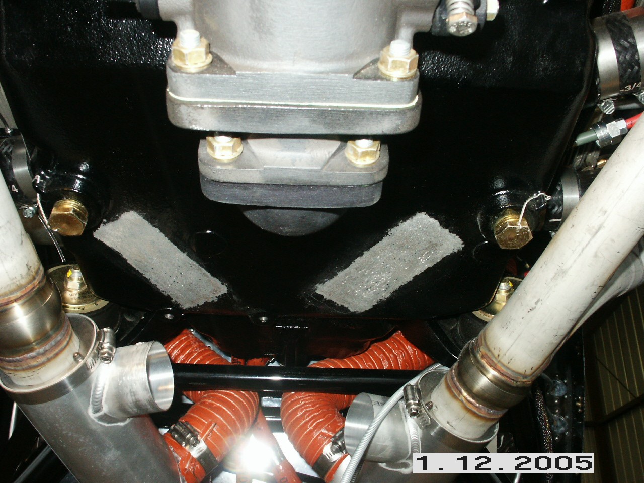
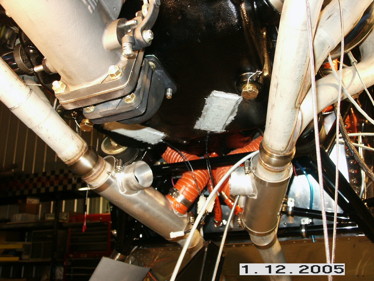
Prior to installing the engine controls, I installed my Reiff crankcase heaters. This was fairly straightforward. First, I scratched the outline of the heating elements on the bottom of the crankcase and used my Dremel to remove all the paint. Then, I used the glue supplied in the heater kit and glued the strips to the bottom per the instructions. I turned on the elements for about 1 hour to let the glue cure and that was it. Once I route the wires for the CHT/EGT probes, I'll secure these wires. My plan is to route the plug up the back of the engine and across the top of the plenum to the oil check door. Next step is to install the EGT/CHT probes. That work begins on the next page. |
||
|
"I am always doing things I can't do -- that's how I get to do them." |