|
|
| Home-->F1 Rocket Project-->Rig/Final Assembly Page 6 |
|
SITE CONTENTS
Please send your comments and suggestions to:
Copyright © 2002-2005 by
|
Links
on this page: Restraint System Carpeting Comm Antenna Instrument Sub-Panels Firewall Protection Instrument Panel |
|
|
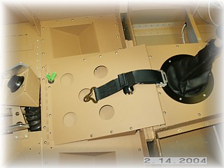
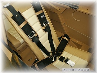
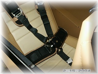
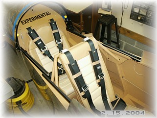
The front seat restraint system is pretty straightforward. I ordered my belts from Mark. The crotch strap and the shoulder straps are just wrapped around their respective mounting brackets. The lap belts are bolted to the fittings. These should be mounted as far aft as you can so that the belt fitting doesn't stab you in the back once the cushion is mounted. The straps then go through the seat back and around your cushion.
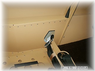
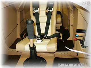
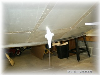
Above is the cut out I made in my rear side panels for the lap belts. These are mounted with bolts, just like the front ones. The shoulder belts are also mounted with bolts. It took a fair amount of fiddling and messing to get everything mounted and to fit correctly.
In the end, I'm happy with the way they turned out.
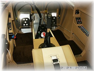
The last step was to install the carpeting. I used some rubber matting underneath the pedals. I glued two layers of "sleeping bag matting" to the floor and placed the carpeting on top of that.
I mounted my bent whip Comm antenna on the centerline of the bottom of the fuselage, just forward of the front stick. This keeps it far enough from the landing gear that reception shouldn't be a problem. My NAV antenna is in the left wing tip and the transponder antenna will be mounted on a plate inside the engine compartment on the bottom of the cowl.
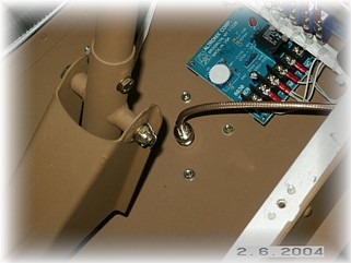
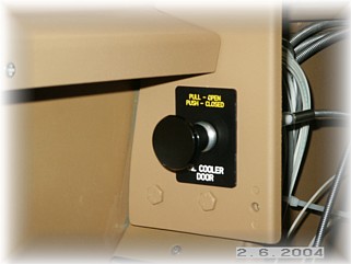
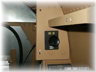
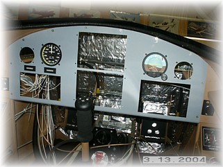
I used the tooling holes in the "wings" of the instrument panel to mount my two ratchet-style control cables. The one on the left controls a sliding door in front of the oil cooler. The right one control the cabin heat valve. I ordered a couple of panels from Front Panel Express to mark these.
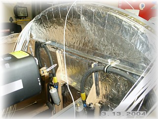
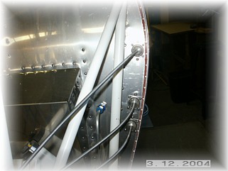
I covered the inside of my firewall with a fire retardant blanket. I also taped the seems with aluminum tape to protect the edges of the blanket. While I was doing that, I went ahead and mounted the cable assemblies for the engine controls.
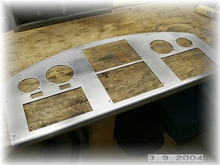
I've finally reached a point where I can start hacking up my instrument panel. I figure that as soon as I cut the holes, some company will offer a "new and Improved" something or other that I will just have to have. Oh well, you can't stop progress. I've mounted the few instruments that I have and I will begin ordering the others soon.
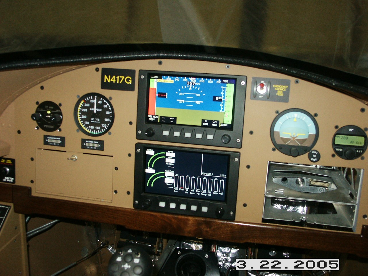
Here's a screen shot of the EFIS displays fired up. I haven't done anything yet to set up the displays but his picture gives you an idea of what they look like. Next I plan to finish out the side panels and install the map box. That work begins on the next page. |
||
|
|
||
|
"Any fool can make things bigger, more complex, and more violent. It takes a touch of genius--and a lot of courage--to move in the opposite direction." - Albert Einstein |