|
|
| Home-->F1 Rocket Project-->Fuselage Page 9 |
|
SITE CONTENTS
Please send your comments and suggestions to: Copyright
© 2008 by
|
Links
on this page: Passenger Seat Panels Rear Headphone Wiring Tail Wheel |
|
|
After getting my bending brake, I decided to go ahead and finish up the panels in the passenger seat area. With the Mk. 2 flap bar, some side panels are needed to cover the flap linkage. I started on the right side first and made an arm rest. I riveted it to the fuselage angle already present. I then went ahead and made a panel that can be removed by screws. The floor mounting will be with screws as well, but I will wait until I pull the floor panels for other things before installing the nut plates there.
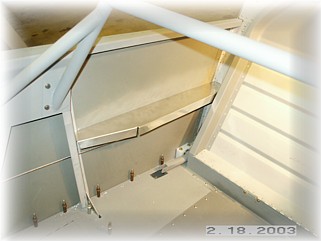
On the left side, the arm rest is a little more complicated. There needs to be a kink in the arm rest to clear the motor when it is fully retracted. I bent an arm rest to fit the area and then marked that angle on the skin. I then fabricated an angle and riveted it to the skin.
Next came the panel. It is like the right one and can be removed by taking out the screws. The only thing to watch out for on this panel is to not put any screws in the area where the motor is. You can see in the left picture where I skipped about three screw holes. This is where the motor tucks up underneath the arm rest and any attachments in this area will interfere with the movement of the motor. While I was at it, I also fabricated a couple of plates so that the area next to the pilot's seat could be used to store some maps.
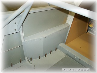
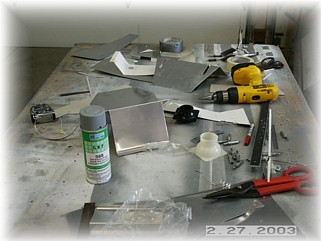
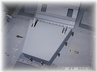
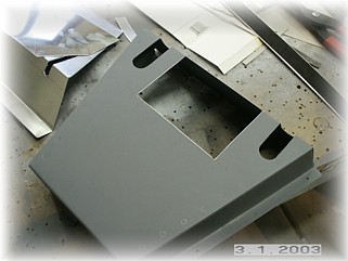
The final rear seat panel to fabricate is the one that covers the rear control stick area. I struggled for about three days before coming up with something that would actually work. I wasted about half a sheet of aluminum making scrap. The keys here were that the panel needs to allow room for the seat belt attachments, cover the area, provide somewhere to mount the rear vent, and not interfere with the passenger's legs. I finally came up with this triangular shaped panel to start with.
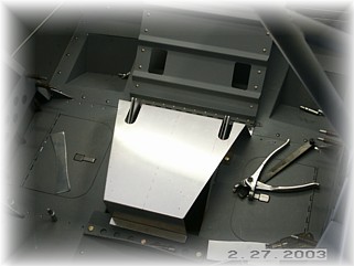
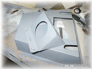
I fabricated some side pieces and riveted the whole thing together. With that settled, I cut out an opening for the vent panel. I wanted the vent panel to mount from underneath so that I could remove the larger panel without disconnecting the fresh air vent hose.
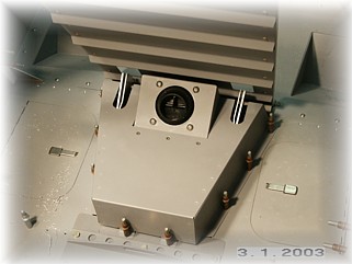
I built the vent panel and made it so it screws to the larger panel. I attached the vent and screwed everything together. This turned out pretty good. I can remove six screws and leave the vent panel in place while removing the larger panel for maintenance. Since the panel is only 3 inches high, this panel will not be noticeable once the passenger seat cushions are put in place. I may even use the other surface area on this panel for other things like a drink holder.
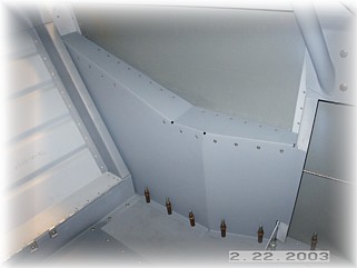
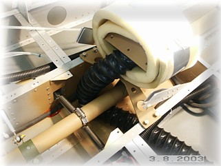
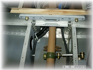
To get the fresh air over to the vent, I installed a bulkhead flange to the side of the fuselage. I will also install one on the outside for the hose that goes to the wing. My reasons for this are twofold. One, I wanted an air tight seal here because it gets cold here in the winter and I don't want a bunch of cold air infiltrating the cabin. Second, I want to be able to disconnect the wing without having to remove the hose from either the vent (a real pain) or from the NACA inlet (even a bigger pain). The hose runs through a hole and around the right side of the control stick, where it is held out of the way by a wire tie. From there it goes up to my removable air vent housing, which is wrapped in foam to protect the finish paint from chipping.
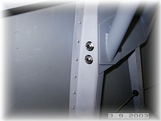
After sitting in the airplane and thinking hard about this, I decided to install the passenger headphone jacks in the left fuselage bulkhead. I chose here because the wires on the headphone are on the left side, and up here, they will be out of the way of legs and feet. Also, I can hide the wires behind the bulkhead. I ran the wires down and inside of the bulkhead and then through a grommet to the other side, behind the flap panel. Be sure that when you install your jacks that you insulate them from the airframe. My jacks came with two plastic washers apiece, one of which had a lip which snapped into the hole. This is important for eliminating noise from your headsets. You only want your audio system grounded at the connection to your audio panel or intercom.
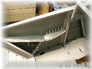
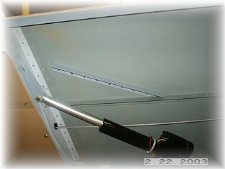
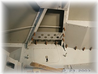
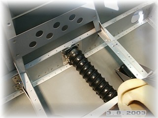
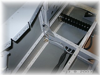
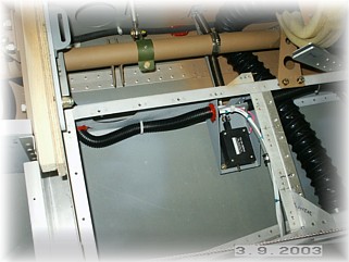
Since the passenger headphones were the last wires to run down the left side, I finished up the wiring runs. I ran the tubing up over the electric trim motor by drilling mounting holes in each side for the tubing. This was a good place to bring in the wire runs from the wings so I mounted a cushion clamp on the underside of the crossing angle and stubbed out the wires. I ran my battery wires down the bottom edges of the central tunnel. I put a couple of the clickbond fasteners in the corners to hold the battery cable and the tubing down and out of the way of the control tube. I will not do much more in this area until the wings are mounted otherwise I won't be able to get in there to install the bolts.
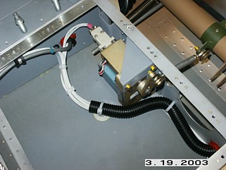
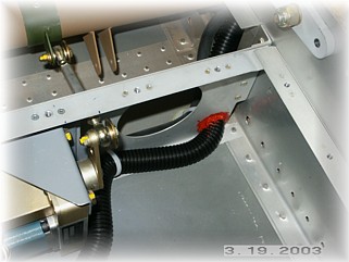
Here are a couple of shots of the right side wiring run as it ducks around the autopilot servo, runs into the center tunnel area, and goes up over the spar.
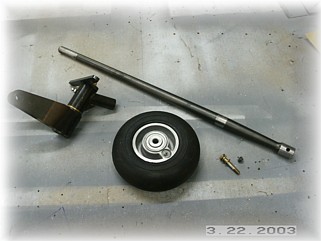
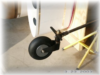
Not much really to report here. I installed everything according to the plans. That spring steel sure requires a sharp drill bit. If it is the least bit dull, the bit goes nowhere. I was over at the sharpener a half dozen times. You'll notice that I cut out a couple of hub caps out of .063 scrap. I like this look better than just the wheel. Later, I'll disassemble and prime all these parts. Next step is to install the wiring and switches for the electric heated seats. That work is on the next page. |
||
|
"Anyone can do any amount of work provided it isn't the work he's supposed
to be doing at the moment." |