|
|
| Home-->F1 Rocket Project-->Fuselage Page 8 |
|
SITE CONTENTS
Please send your comments and suggestions to: Copyright
© 2008 by
|
Links
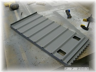
on this page: Pilot's Seat Back Boot Cowl/Cowl Flange |
|
|
First thing I did was gather up all the parts needed to mount the pilot's seat back. This included the seat back braces. After contemplating the assembly sequence, I concluded that I first needed to mount the seat back braces on each side of the fuselage. Using the dimension from the plans of where the center of the tubes needed to be aft of the firewall, I drilled each set of braces to the reinforcing plate. Be careful here to measure your distance at the point you intend to install the cross brace. The higher up you go, the further the measurement becomes. After studying all the measurements, I concluded that the cross brace would go just above the welds for the side tubes.
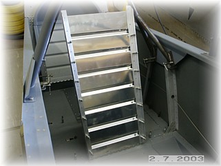
Then I assembled the seat back per the dimensions in the plans. All the parts are supplied long so you can make the height of the seat back just about any height you'd like. With everything drilled together, I tested it in the fuselage. I also marked the location on the support tubes for the cross tube. It needs to be at least 1/8" above the top of the seat back so that the seat belt harnesses will fit.
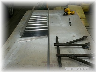
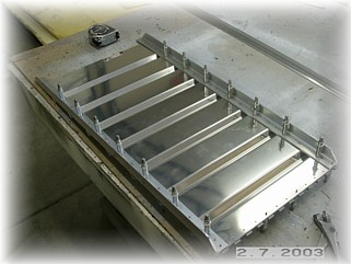
Once I was sure everything fit, I drilled the holes up to the correct size, cleaned, primed, and riveted everything together. I also cut the slots for the seat belts. These may not be the final size, but it's a start. The plans are not very clear on the rivet sizes and locations. I used -4 rivets in the thick angle but only -3 along the top and bottom. I don't like to squeeze -4 rivets into the hinge since the hinge is so soft. It tends to distort. I used 1" spacing so I'm pretty sure that the hinge isn't going to fall off.
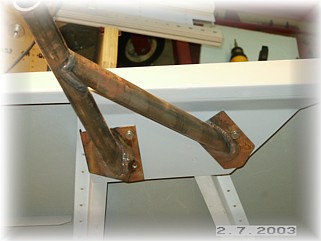
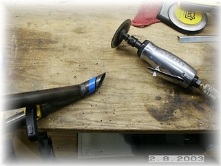
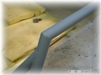
Using the marks on the tube for the height of the cross tube, I began to cut the tubes. I used a protractor and angle level to approximate 30 degrees. Something that is more important than the angle is to make sure you cut the face of the angle in the same vertical plane on both sides. Small gaps in the angle can be filled when welding but if the vertical planes are off, you will not have a smooth transition between the tubes. I used my die grinder to make the initial cuts and then I used my bench grinder to get a custom fit. Once I was happy with the fit, I tack welded it all bolted up in the fuselage. I then took it over to the bench to finish up the welding. I acetylene welded mine because that's what I have in my shop. After welding, I used my die grinder to smooth out the welds for a nice, clean look.
After priming the tubes, I bolted everything up. It fits well. One last note. I did a fair amount of grinding on the mounting pads of the support tubes to get them to fit correctly on the reinforcing plate. I didn't want any part of the steel mounting pads overhanging the reinforcing plate. That would be a good place for clothing or fingers to get caught on. Again, mount the pads where you need to get the right aft measurement and then trim any overhang to get a good fit.
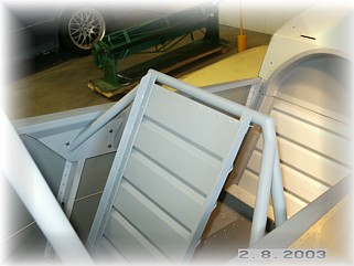
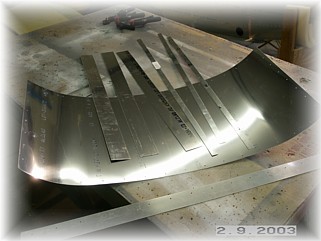
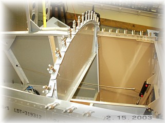
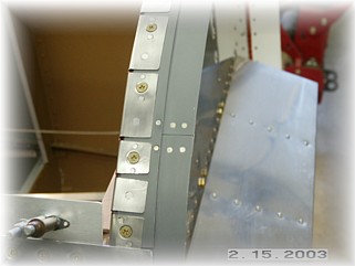
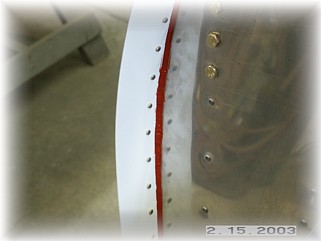
After collecting up the parts for the cowl flange and boot cowl, I contemplated how to make all this come together correctly. Installing the cowl flange is a critical operation that will show to everyone who looks at your airplane, so you want it to look good. I first tried to use the spacer strips provided in the kit, but I ended up throwing them out. They are too narrow and they don't extend all the way out to the edge of the skin. I think it looks much better if the spacer fills the whole space. I cut some replacements out of .063 aluminum and drilled them to the flange. The trick here is to allow enough space along the aft edge of the spacer to stay away from the rolled edge of the firewall flanges. You must get the spacer to lay flat and parallel to the skins.
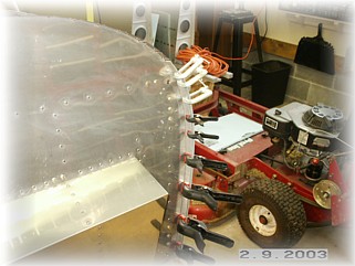
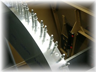
Clamping along the top is very critical. In order for the boot cowl to lay flat, you've got to get the holes drilled with the skins as tight as possible. Once the spacers are installed, I installed the cowl flange strips provided in the kit. These were installed according to the plans. Another trick is to make sure that the parts are pre-bent into the shape of the firewall before drilling them. This is very important. It will help to get the skin to lay flat and not pucker. After drilling the holes along the top through the boot cowl, I removed the boot cowl and clamped up the parts again and drilled the other holes along the top. Again, clamp everything tight as you can. Align the holes with a punch and then set the clamps. Before drilling the plate that covers the flange joint, re-attach the boot cowl. This will hold the firewall at the proper angle.
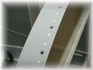
With everything drilled, I went ahead and primed the parts. While they were drying, I went ahead and attached the nut plates to the rest of the mounting area for the boot cowl. I then went ahead and started riveting everything together. I went slowly and held the skin with clamps to get a tight set with the rivets. Along the top, the stainless is dimpled and the spacer underneath is countersunk.
On the front flange, I discovered too late that the rivet for the nut plates are supposed to go through the flange as well. So, I just screwed the panel down and drilled additional mounting holes just outboard of each nut plate. That worked out just fine.
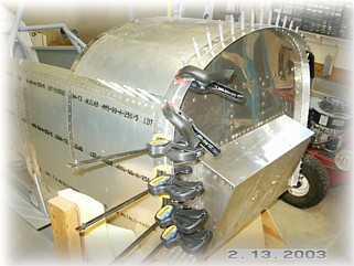
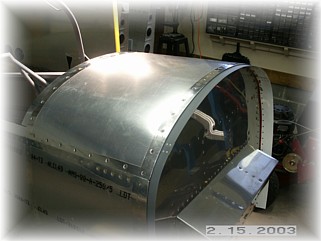
After priming, I painted the backside of the cowl flange white. It is easier to do this now rather than try and paint it later. After I was done riveting, I installed a bead of high temp RTV all along the edge to seal the firewall from the cockpit. Now comes the moment of truth, attaching the boot cowl with screws. If anything got out of alignment, there will be a pucker between the screws. Fortunately, I got the boot cowl to lay flat around the entire perimeter. Whew! I was worried for a while because after three days all I had was a pile of useless parts and rivet holes drilled all over the place. In the end, it turned out pretty good. Next, I plan to fabricate and install the remaining rear seat panels. |
||
|
"Convictions are more dangerous enemies of truth than lies." |