|
|
| Home-->F1 Rocket Project-->Fuselage Page 7 |
|
SITE CONTENTS
Please send your comments and suggestions to: Copyright
© 2008 by
|
Links
on this page: Rudder Pedals Instrument Panel Canopy Rail |
|
|
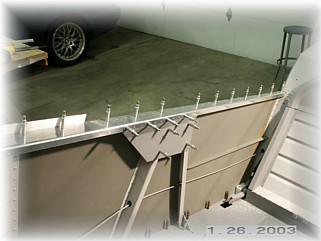
The first thing I did was install the two reinforcing angles to the firewall. The bottom angle is the larger of the two and was installed as far down on the engine mount angles as I could to allow sufficient room for the firewall attachment bolts. The upper angle was drilled using the pilot holes.
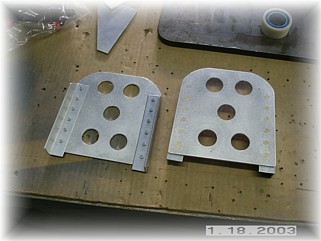
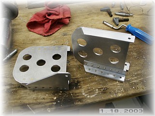
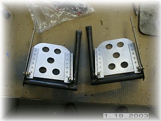
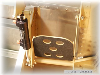
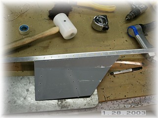
I assembled the pedals first. After drilling some 1" lightening holes, I riveted the angle brackets to the back of the pedals per the plans. Remember that the rivets should be countersunk so that the front of the pedal is smooth. Next, I attached the master cylinder brackets to the side of the pedals. Remember to make a left and a right pedal. These rivets are also countersunk.
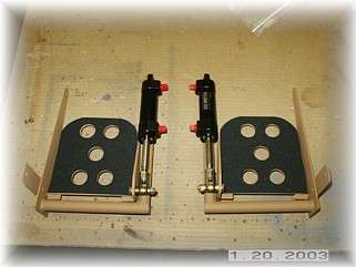
I then drilled the mounting hole in the brake pedal arms and trial fit the pedals using the hardware provided. I ended up using some slightly longer bolts on the inside mounts. After I was satisfied that everything moved smoothly, I disassembled everything and painted up the brackets and the pedals. On the front face of the pedals, I installed some wing walk material and cut out the lightening holes with a razor knife.
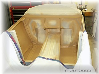
At this point I discovered a problem. I don't have a drill or drill attachment that can get into the firewall fittings to drill the holes to final size. So I ordered a right hand drill attachment from Avery Tools, with an assortment of drill bit sizes. In the mean time, I masked off the stainless steel and finish painted the forward compartment. I don't like installing stuff and then taking it all off again to paint so I decided to do it now. I can always touch up any marks in the paint as I go.
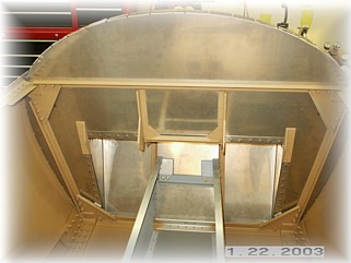
After drilling the holes, I installed the pedals. I'm not happy with the routing of the rudder cables so I'm ordering some steel tubing. I plan to run some tubing from pedals back through the first bulkhead and attach the cables there. I believe that this is the way the Harmon Rockets do it.
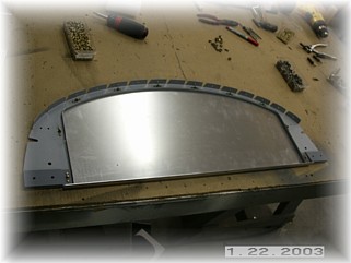
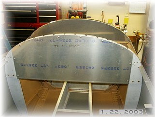
To install the instrument panel, it is important to familiarize yourself with the way it goes together. It is pretty simple once you get a mental picture of how the pieces go. I first drilled and riveted the doublers to the fuselage ribs.
Then I riveted the nut plates to the sub-panel and screwed the panel to the sub-panel to stiffen it up. I then clamped and final drilled the two wedges in concert with the panel as it was held in position on the airframe. I then disassembled everything, cleaned up the parts and did the final assembly.
With the panel in place, I can now begin imagining what it's going to look like filled with avionics.
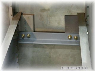
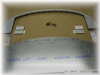
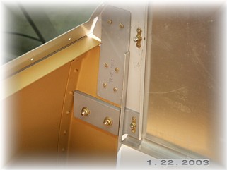
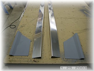
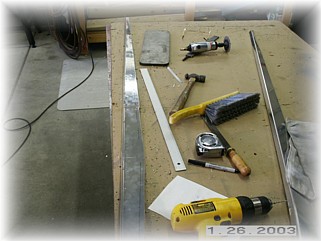
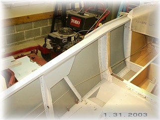
To install the canopy rail, I laid out the parts on my bench and determined the location of the mounting holes. I pre-drilled the rails over on my bench and then drilled the rails to the fuselage. There are three areas to avoid putting rivets. You want to avoid the area around the fuselage ribs, around the spar ribs, and the two mounting locations of the windshield bow. I just laid out the 1 1/4 spacing along the length of the part and eliminated the offending rivet locations.
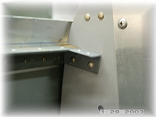
After mounting the rail to the fuselage, I went ahead and drilled the reinforcing plate in position. I took the whole assembly over to the bench and riveted the two parts together. It this picture you'll notice that I used -3 rivets. I discovered my mistake before I did the final riveting and enlarged all the rivet holes for -4 rivets. I have this habit of reviewing the plans one more time before I set a rivet and this time, it saved me.
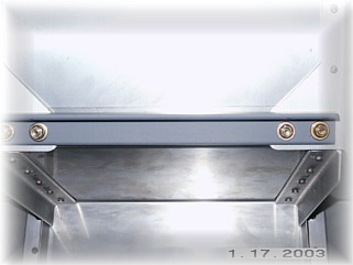
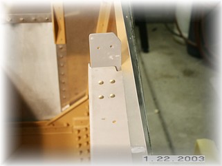
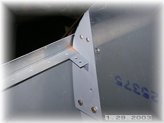
At the front of the panel, the plans show a bent plate on the top of the rail to attach the rail to the instrument panel bulkhead. Instead, I took a couple of pieces of .063 angle and made a couple of clips. The only caveat to this change is that I had to insert a spacer between the panel bulkhead and the fuselage bulkhead because the panel is tilting away from the bulkhead. I inserted a scrap piece of aluminum between the two panels before I riveted the angles on.
All that was left was to rivet everything together. I had to use some pop rivets in the upper three holes of the reinforcing plate because I don't have a backing plate that will fit up in there. Next up is to fabricate, weld, and mount the pilots seat back support bar. That begins on the next page. |
||
|
"Well begun is half done." |