|
|
| Home-->F1 Rocket Project-->Rudder Page 2 |
|
SITE CONTENTS
Please send your comments and suggestions to: Copyright
© 2002-2005 by
|
Links
on this page: Jig Skins Rivet Rudder Roll Leading Edge |
|
|
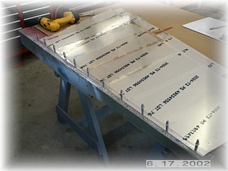
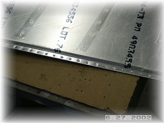
Jig Skins Before the skins can be jigged to the skeleton, the trailing edge must be prepped. I followed the plans and laid the skin upside down and final drilled the holes through the skin and through the reinforcing strip. I used the strip as a guide to drill the other skin then I cleaned and deburred the holes and reassembled the two skins together. I left the reinforcing strip long and extending beyond the skins. I saw no reason to trim it at this point in the construction. I want to fit the fairing on and then decide how to finish the end of the edge. Some builders have hinted at rounding the edges of the reinforcing strip to keep from catching your cleaning cloth on it once the airplane is finished.
On my worktable, I put the skeleton inside the skins and began positioning the skin, clamping it to the skeleton as I went. I started at the bottom, around the cut out for the rudder horn. The spar should sit down in the skins so that the web of the spar is just below the bottom edge of the cutouts. Once it all looked good, I mounted it in the jig and checked the trailing edge to make sure it was straight. I started drilling the attach holes in the center of the front spar and worked my way towards each end. Once both sides were done in this manner, I drilled down the bottom rib on both sides.
I took the rudder out of the jig to finish drilling the top rib. I squared the edge of the counterweight skin with the spar web and drilled the remaining holes. Remember to mark the extra line of rivets beside the top rib rivets and drill them at this time too.
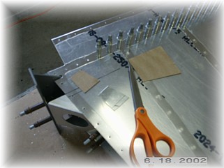
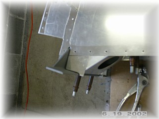
All that's left to drill are the rudder horn brace and the rudder fairing attachment doublers. I used the holes in the skin/rib as a guide to drill the holes through the doublers. While you are working down in this area of the rudder, you have the option to address the rudder horn opening now rather than later. When the rudder bottom fairing is cut and mounted, you will be left with a big square opening behind and above the rudder horn. That's because the fairing will need to have a square opening cut into it in order to fit around the rudder horn. Some builders just leave this open. Others fill it with an assortment of balsa wood, fiberglass, bondo, etc during the finishing phase of their project.
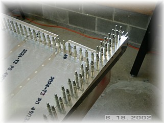
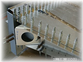
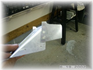
I've found that there is enough space on the side of the rudder horn brace to rivet on a spacer. I cut out a cardboard template and used it to fashion out a spacer skin out of .062 aluminum plate. I used the thicker aluminum because it will match up better with the fiberglass, which is thicker than the surrounding aluminum. There are three things to watch for. Ensure that the aft edge of the spacer is parallel with the forward edge of the rudder horn. This will allow you to make a square cut in the fairing. Second, there is no room for error in drilling the two -3 countersunk rivets. Mark and drill them carefully. These will be sufficient to hold the spacers in place and will give a clean and finished look to the fairing install. Finally, you have to leave enough room on the horn brace to install a pop rivet/nutplate for attaching the fairing. Only make the spacer wide enough to give you room to rivet it to the brace while still giving you enough room for the rivet/nutplate attachment point for the fairing.
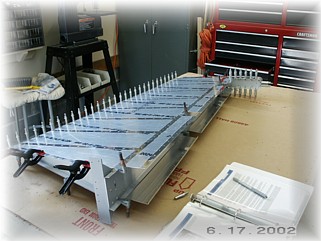
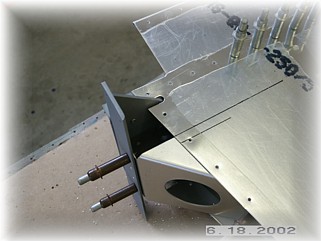
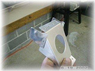
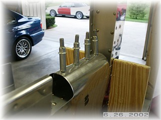
This is what you end up with, the rudder horn brace looks like it has wings attached to the sides. This will slip into place before the skins are riveted on. You might be able to install the spacers once the rudder is finished but you would have to use pop rivets to attach them. With the rudder disassembled, I've cleaned, deburred, dimpled, and primed (as necessary) all the parts. It is now reassembled on the bench and placed in the jig for final riveting.
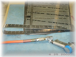
First step is to rivet the inboard line of rivets in the counterweight skin. You have to do these first because they will not be accessible once the skeleton is inserted. I used my backing plate to rivet the skins together. I then slipped the skeleton inside and placed the rudder back in the jig. Again, I started riveting from the center of the spar outward and downward.
Over on the bench I riveted the trailing edge. This was harder than I thought. The shop side, which is made using another 3/32 cupped rivet set, tends to pucker the thin skin around the hole. I went ahead and set about eight rivets at a time and then went back with a hammer, bucking bar, and my backing plate and hammered the skin smooth again. This worked out okay. Once I was finished riveting the entire edge, I filed it smooth and rounded the rear edge.
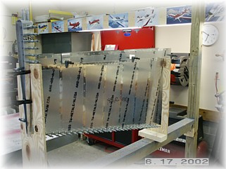
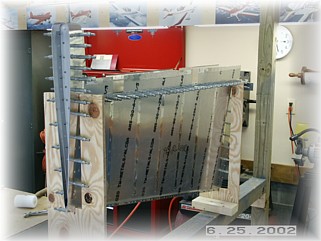
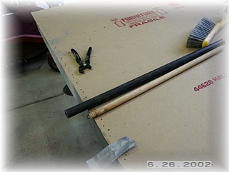
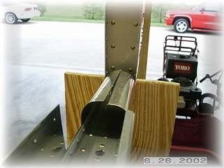
One of the more unpleasant tasks is rounding the leading edge skins. I've found the job easier to do using two different size rollers. The first is a piece of one inch pipe. The second is about a 5/8 inch broom handle. I first make the major bend with the pipe kind of near the middle of the skin. I then use the broom handle near the top to get the edge to roller over.
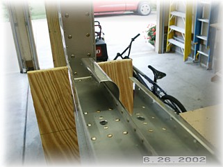
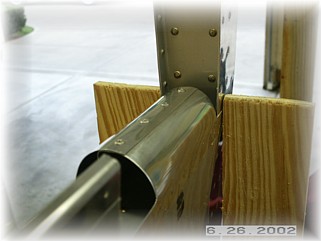
When you're done with the general bending, it looks like this. I then do the rest by hand to get the joint to lay together well. I also use an edge rolling tool along the edge of the top skin to get it lay flat without puckering. Do this gently because it doesn't take much on these thin skins. I work from the tip back, doing one section at a time.
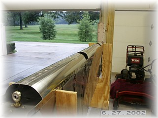
After I get it to lay flat, I carefully drill the #40 holes to #30, disassemble and debur the holes, and then reassemble and rivet. When setting these pop rivets, carefully square the rivet head to the skin before pulling the rivets in order to get the rivets to lay flat against the skin. When you're all done, it should look something like this. |
||
|
"If
you see a snake, just kill it - don't appoint a committee on snakes." |