|
|
| Home-->F1 Rocket Project-->Elevators Page 3 |
|
SITE CONTENTS
Please send your comments and suggestions to: Copyright
© 2008 by
|
Links
on this page: Left Elevator Trim Motor Mount Attach Left Elevator Skins Elevator Trim Hinge Pin Rivet Left Elevator |
|
| Left Elevator Trim Motor Mount
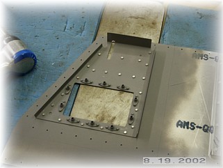
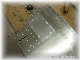
I riveted the reinforcing bracket to the left bottom elevator skin using my backing plate. I then mounted the cover plate using stainless steel #6 screws.
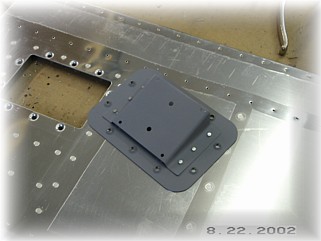
With the cover plate secured, I centered the trim motor mount in the opening and drilled it to the cover. The cover and mount are then cleaned, dimpled, and riveted together. I will mount the motor, wiring, and other hardware once the trim is finished and mounted to the elevator.
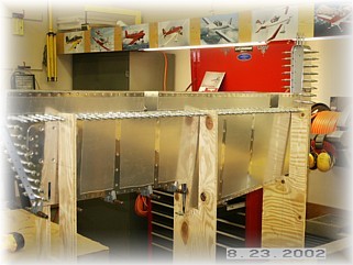
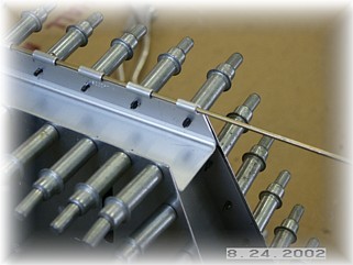
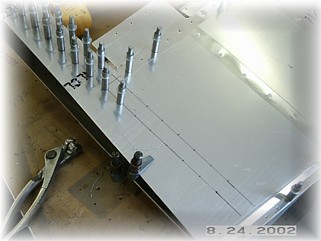
I then placed the skeleton and the skins into the jig and clamped them together for drilling. I drilled all the holes in the same way as on the other pieces, starting in the middle of the spar and working out and down. I did not drill the trim spar at this time. Once all the holes were drilled, I removed the assembly from the jig and brought it over to the table. I aligned the spar in the opening and drilled only the bottom skin holes. This provides enough rigidity so that I can align the hinge before drilling the top skin holes.
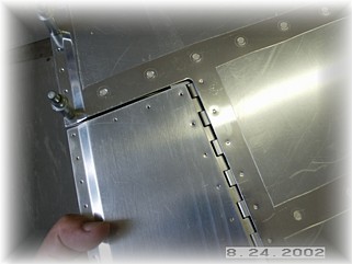
The top skin holes are drilled through the spar and the hinge while they are clamped in place. In order to end up with even spacing between the trim tab and the elevator along the hinge line, you need to check to see what spacing is needed. Ideally, the space between the forward edge of the trim tab and the hinge will be the same space as from the rear edge of the elevator skin and the hinge. Once that is checked and set, I clamped the hinge to the spar and to the skin and drilled all the holes.
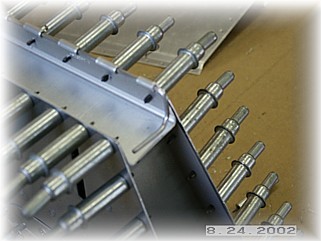
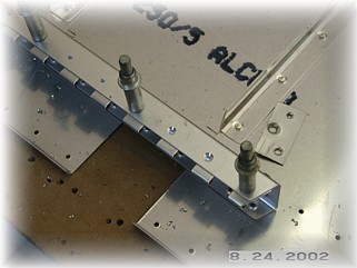
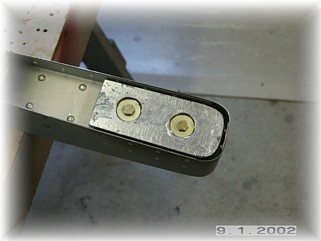
As supplied in the kit, the hinge is longer than what's needed. When you trim the hinge to length, be sure to NOT cut the hinge pin. Leave it long and extending past the end of the elevator as shown above. Now bend the hinge pin so that it will lay across the web of the spar.
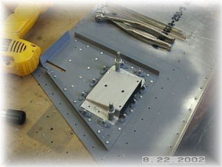
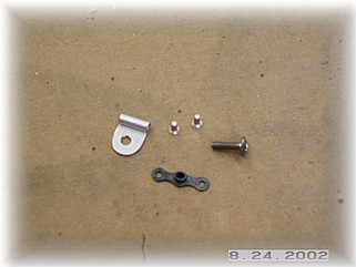
Take a spare piece of hinge and cut out one eye. Drill a hole in it for a #6 screw. Slip it over the hinge pin and locate the position of the screw hole in the web of the spar. Remove everything and attach a #6 nut plate behind the hole. The nut plate will fit on the forward side of the elevator trim spar web where it extends past the edge of the inside elevator rib. When you're done, you'll find that you will be able to get a long bladed screwdriver on the screw even with the trim tab mounted and in-place.
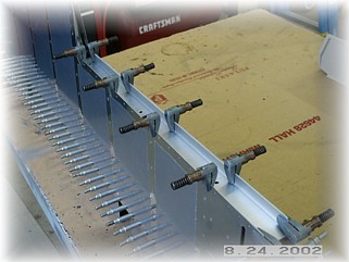
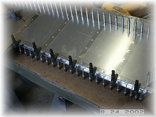
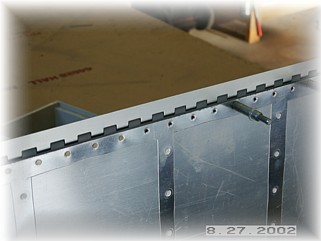
The only other drilling left to do on the skins is to finish the counterweight skins. I extended the rivet lines down the skin and drilled the holes on both sides. Again, make sure the tip is square to the forward face of the elevator spar before drilling any of these holes.
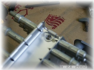
While cleaning and dimpling the parts in preparation for riveting, the elevator trim spar is handled differently than the other parts. In order to prevent distortion to the hinge when it is riveted, the skin is dimpled but the spar is countersunk. This eliminates the need dimple the hinge. To help with countersinking the spar, I clecoed the hinge to the spar. The extra depth helps to stabilize the countersink bit in the hole and prevents it from chattering.
I began riveting the assembly together by starting with the trim tab spar. Note that it when you rivet the hinge, it helps to pin the other half of the hinge to the assembly to help keep the hinge straight. The rest of the assembly is riveted in the jig just like the others, starting in the center and working outward.
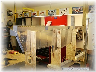
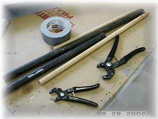
There are a couple of clean-up jobs before moving on to the trim tab. I went ahead and rolled the leading edge skins now. That's so I can dismantle the jig and get it out of the middle of my shop. As with the rudder, I use two different size pipes to roll the front edge. The larger is a 1 inch iron pipe that I use in the center of the skin. The other is a 5/8 inch broom handle which I use on the leading edge to get it to roll under.
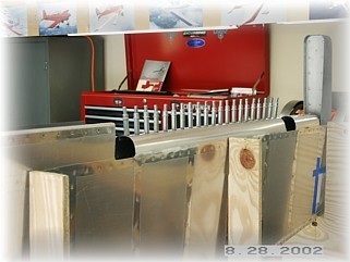
When you're all done, it should look something like this.
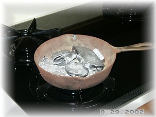
I also wanted to get the counter weights made and attached. This is where things got out of hand. Instead of just pouring the weights in place, I decided to fabricate a reusable mold so that I could make sets of weights for other builders. This turned out to be a little bigger job than I thought, but I did manage to get a reasonably good mold made.
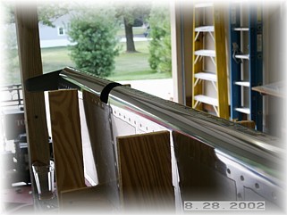
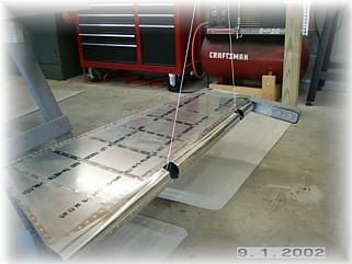
It's hard to see in the picture, but the right elevator is hanging slightly nose down but it is very slight. Once I get the tips and paint on, I will make final adjustments so that the balance is neutral. I can't balance the left elevator until I finish and install the trim tab so that's what I'll do next. |
||
|
"Expect
problems and eat them for breakfast." |